In industrial ventilation and dust collection, the ductwork is often viewed as a passive component; simple piping connecting a hood to a collector. This misconception is a primary driver of system inefficiency, excessive energy consumption, and safety compliance failures.
The ducting network is the circulatory system of any manufacturing facility. Just as arterial blockage or leakage compromises human health, duct leakage compromises system health. For engineers and facility managers, understanding the physics of duct leakage is not merely about preventing a mess on the floor; it is about maintaining specific static pressure setpoints, ensuring transport velocities, and adhering to strict regulatory standards.
This article explores the fluid dynamics behind duct leakage, its measurable impact on system performance, and why modular, clamp-together ducting designs offer a superior engineering solution to traditional joining methods.
To understand the severity of leakage, one must first revisit the fundamental principles of airflow. A dust collection system operates on a pressure differential. The fan creates a region of low pressure (suction) relative to the ambient atmospheric pressure. Air moves from the high-pressure zone (the factory floor) to the low-pressure zone (the duct interior) to equalize this difference.
Leakage occurs at any point where the boundary of the ductwork is compromised—typically at joints, seams, or physical damage points.
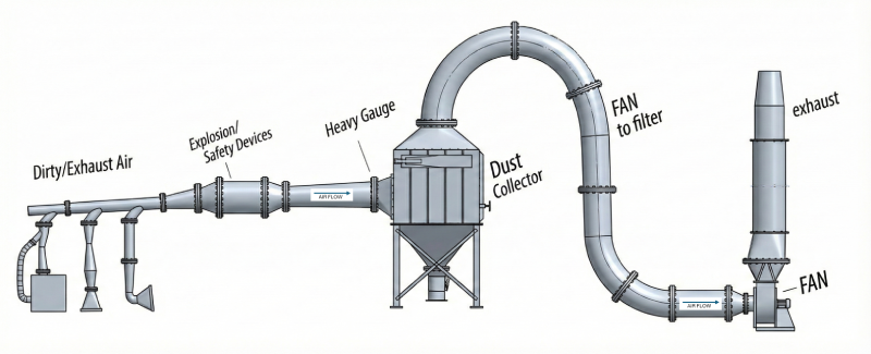
On the suction side of the system (pre-fan/collector), the internal pressure is negative relative to the ambient air. A leak here does not expel dust; it sucks air in. This "parasitic air" has two immediate consequences:
On the return side (post-fan), or in positive pressure conveying systems, the internal pressure is higher than ambient. A leak here expels air and fine particulate into the facility. This is the primary source of "fugitive dust," which presents immediate respiratory hazards and combustible dust risks.

From a facility management perspective, air is a utility. Moving it costs electricity (horsepower). Leakage is, quite literally, air you have paid to move that is doing no work.
“Leakage is air you have paid to move that is doing no work.”
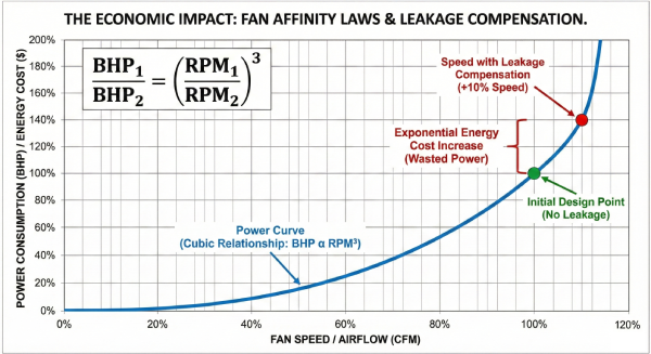
The cost of leakage is governed by the Fan Affinity Laws (these laws describe how airflow, pressure, and power change when fan speed is modified). These laws dictate that while flow varies directly with speed, power consumption (BHP) varies with the cube of the speed.
In a system with significant leakage, operators often attempt to compensate for the loss of suction at the hood by ramping up the fan speed (via a Variable Frequency Drive or VFD) or opening dampers. Because the power requirement increases cubically, a small increase in fan speed to overcome leakage results in a massive spike in energy consumption.
Consider a system designed for 10,000 CFM at 10” wg (water gauge). If poor duct joining results in 15% leakage, the system is essentially processing 1,500 CFM of useless air. The fan motor is still driving that load, but the energy is wasted. Over a year of 24/7 operation, the kilowatt-hour cost of moving that parasitic air—combined with the conditioning costs if that air is heated or cooled—can run into the tens of thousands of dollars.
The implications of duct leakage extend beyond efficiency into the realm of strict liability and safety compliance.
The National Fire Protection Association (NFPA) standard NFPA 660 (Standard for Combustible Dusts), is explicit regarding dust accumulation. (NFPA 660 consolidates earlier dust-related NFPA standards including 61, 484, 652, 654, 655, and 664.)
Leakage in positive pressure ducts sprays fine dust onto elevated surfaces—beams, light fixtures, and piping. This "fugitive dust" is the most dangerous kind; it is dry, oxygenated, and has a high surface-area-to-mass ratio. NFPA identifies the threshold thickness for hazardous dust accumulation as 1/32 of an inch (0.8 mm), roughly the thickness of a paperclip or dime. If a primary explosion occurs in a collector, the shockwave can dislodge this settled fugitive dust, creating a secondary dust cloud that ignites and causes a catastrophic structural explosion.
Furthermore, leakage on the negative pressure side can cause material dropout within the duct due to velocity loss. Pockets of settled fuel (dust) inside the ductwork are a prime location for localized fires or deflagrations.
The Occupational Safety and Health Administration (OSHA) sets Permissible Exposure Limits (PELs) for various particulates. If duct leakage reduces the capture efficiency at the source hood, dust escapes into the operator's breathing zone. A system that was engineered to meet ACGIH guidelines can fail an industrial hygiene audit simply because the duct joints are not sealed, rendering the capture velocity insufficient.
Unaddressed, these conditions can also negatively impact liability insurance rates, or even threaten passing annual inspections.
To solve the leakage problem, we must analyze where it occurs. In industrial ventilation, the weakness is rarely the straight pipe; it is the connection.
“In industrial ventilation, the weakness is rarely the straight pipe; it is the connection.”

The "contractor standard" often involves inserting one cut end of spiral pipe into another and securing it with sheet metal screws.
Flanges offer a better seal than screws but introduce installation variables.
Welded ducting is the gold standard for sealing (zero leakage) but is often impractical for general dust collection due to:
Nordfab’s Quick-Fit® (QF) clamp-together ducting was designed specifically to address the deficiencies of traditional joining methods regarding leakage, friction loss, and modularity.
Unlike the friction-fit of spiral pipe or the torque-dependence of flanges, Quick-Fit utilizes a mechanical compression principle. The duct ends are rolled outward. A barrel-type clamp with a built-in gasket wraps around these rolled ends.
When the clamp is closed, it exerts uniform radial pressure around the circumference of the joint, compressing the gasket between the two rolled ends. This eliminates the "pinched gasket" issue found in bolted flanges. The gasket material (standard Nitrile, or options for silicone or Viton® for high heat) is chemically resistant and maintains elasticity, ensuring the seal holds even under vibration.
From a fluid dynamics standpoint, the QF joint is superior because it maintains a smooth internal surface. There are no screws penetrating the airstream. The rolled ends meet flush, minimizing the step-change in the pipe wall. This reduces the Darcy-Weisbach friction factor, meaning the system inherently has lower static pressure loss (resistance) per linear foot compared to screwed spiral ducting.
Leakage often develops years after installation. Why? Because factory layouts change. A machine is moved, and the ducting must be re-routed.
It is important to quantify performance. In comparative leak testing, clamp-together ducting consistently outperforms spiral/screw, riveted, and poorly executed flanged systems.
For engineers designing systems, specifying clamp-together ducting allows for tighter tolerances in fan sizing. Because the "leakage factor" in the calculation can be significantly reduced, the fan does not need to be vastly oversized to account for anticipated losses. This results in lower capital expenditure on the fan, and lower operational expenditure (OPEX) over the life of the system.
Duct leakage is not an inevitable byproduct of industrial ventilation; it is a symptom of joining technology that has not kept pace with modern engineering standards.
For facility managers and engineers, the choice of ducting impacts the "Triple Bottom Line" of the plant:
Nordfab’s Quick-Fit® system addresses the physics of leakage through precision-rolled ends and uniform gasket compression. It transforms the ducting network from a potential liability into a verified, high-performance asset.
When designing or retrofitting a dust collection system, look beyond the initial material cost per foot. Consider the cost of the air you are losing, the compliance risks you are assuming, and the labor required to fix it. When you run the numbers, a sealed, modular system is the only engineering choice that makes sense.
Is your facility losing pressure? Nordfab offers tools to assist engineers in designing efficient, leak-free systems.
Request a project review with a Nordfab Ducting Specialist.